

How to setup a Site-to-Site VPN connection between two ATP/VPN series appliances.
Introduction
This guide will explain how to configure a site-to-site VPN connection as shown in the picture below:
In the above scenario the clients at the Branch office wants to be able to access the Headquarters entire LAN subnet and vice versa. The setup will be the same regardless what ATP/VPN model you are using. In this example we will be looking at a two ATP500.
To setup this scenario you need to configure the following in both ATP/VPN:
- Address object for remote subnet.
- VPN Gateway.
- VPN Connection.
After configuring these three things on both ATP/VPN, you will have established the connection.
Table of Content
ATP500 #1
Creating the Address Object
Creating VPN Gateway
Creating VPN Connection
ATP500 #2
Creating the Address Object
Creating VPN Gateway
Creating VPN Connection
ATP500 #1
Creating the Address Object
Go to Configuration(![]() ) → Object → Address and click the Add button.
) → Object → Address and click the Add button.
Now create a Subnet address that contains the LAN Subnet of the opposite ATP/VPN as shown in the picture below: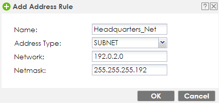
Creating VPN Gateway
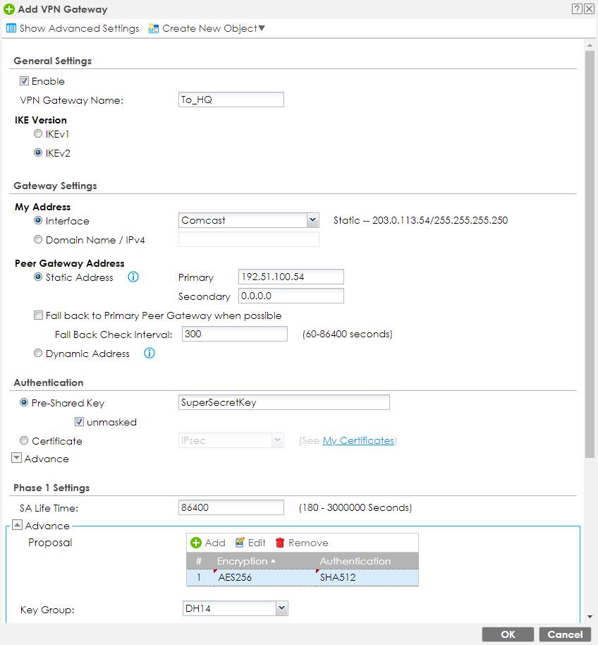
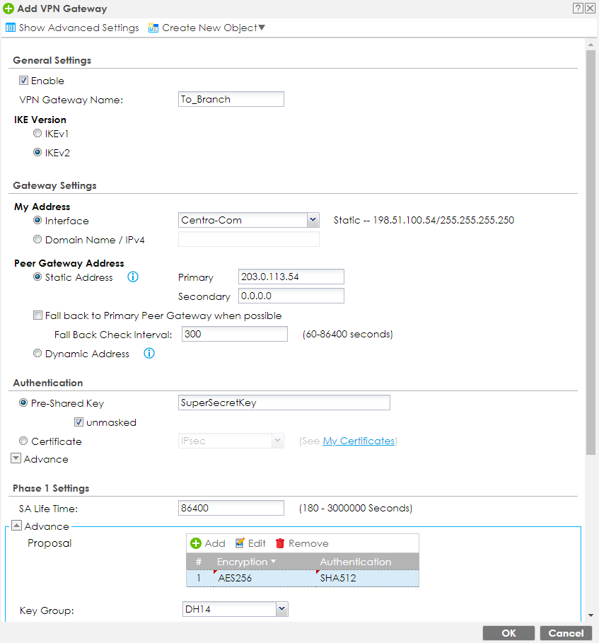
Go to Configuration(![]() ) → VPN → IPSec VPN → VPN Gateway and click the Add button. Verify the following information:
) → VPN → IPSec VPN → VPN Gateway and click the Add button. Verify the following information:
- Enable - This should be checked
- VPN Gateway Name - Provide a name for the gateway rule
- IKE Version - Select desired IKE version (IKEv2 is highly recommended. Both sites need to use the same IKE version)
- My Address - Make sure the correct WAN interface is selected
- Peer Gateway Address - Enter the remote appliance WAN IP/FQDN/DDNS
- Pre-Shared Key - Enter a key for the VPN tunnel [this key must match on both VPN appliances]
- Proposal - Select the desired Encryption and Authentication algorithm [these settings must match the remote appliance]
- Key Group - Select the desired DH group [this setting must match the remote appliance]
- Click OK to save the settings
Creating VPN Connection
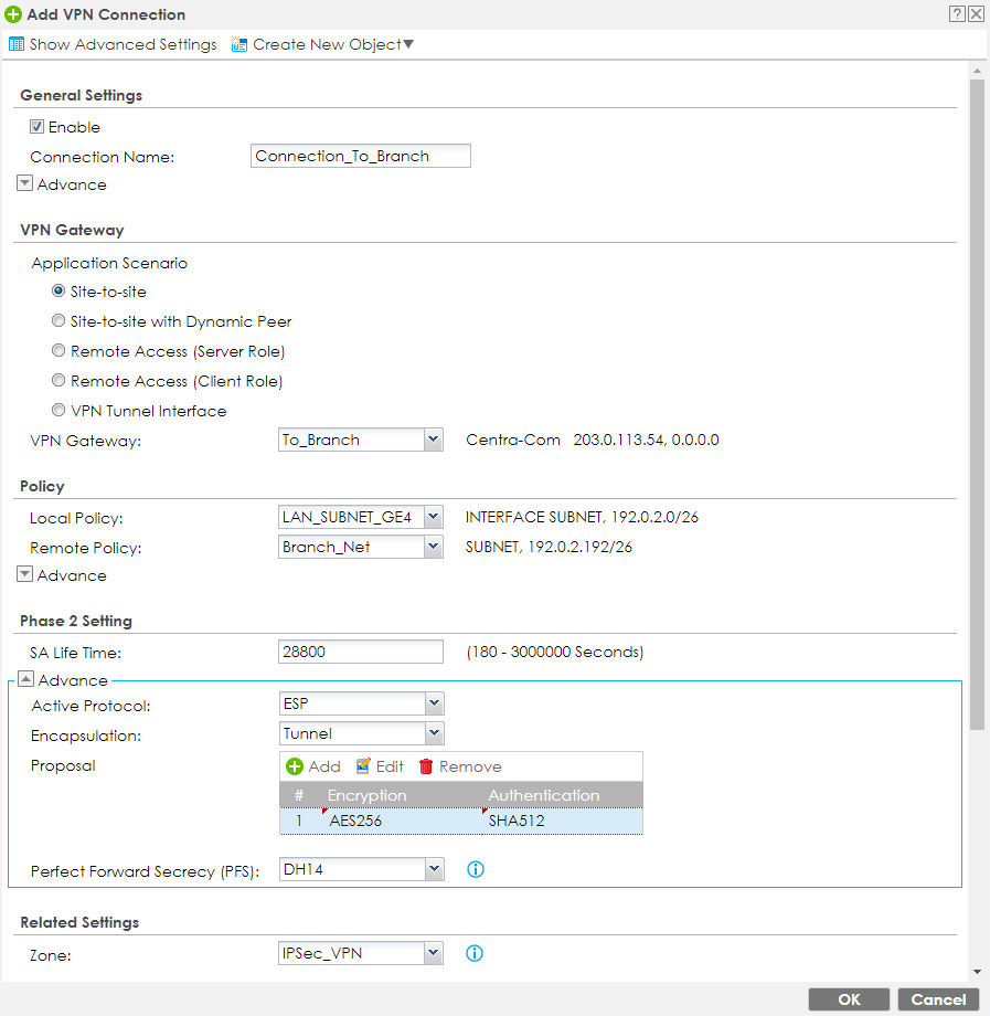
Go to Configuration(![]() ) → VPN → IPSec VPN → VPN Connection and click the Add button. Verify the following information:
) → VPN → IPSec VPN → VPN Connection and click the Add button. Verify the following information:
- Enable - This should be checked
- Connection Name - Provide a name for the connection rule
- Application Scenario - Select Site-to-Site
- VPN Gateway - Select the name of the VPN Gateway rule you created on the previous step
- Local Policy - Select the address object for the local LAN subnet [the local policy specifies what "local IP addresses" (ATP500 #1) the nodes on the "remote site" (ATP500 #2) have access over on this gateway]
- Remote Policy - Select the address object created for the remote networks subnet [the remote policy specifies which "remote IPs" (ATP500 #2) the "local network" (ATP500 #1) can communicate with]
- Proposal - Select the desired Encryption and Authentication algorithm [these settings must match the remote appliance]
- Perfect Forward Secrecy - [optional] select the DH group you wish to use [this setting must match remote appliance]
- Zone - Make sure the VPN rule is part of the IPSec_VPN zone [if not a member of this zone, the Firewall/Policy Control may block traffic flow]
- Click OK to save the settings

You have now finished the required configurations on the ATP500 #1.
ATP500 #2
Creating the address object
Go to Configuration(![]() ) → Object → Address and click the Add button.
) → Object → Address and click the Add button.
Now create a Subnet address that contains the LAN Subnet of the opposite ATP/VPN as shown in the picture below: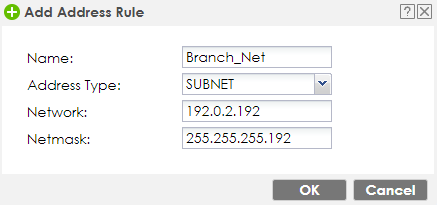
Creating VPN Gateway
Go to Configuration(![]() ) → VPN → IPSec VPN → VPN Gateway and click the Add button.
) → VPN → IPSec VPN → VPN Gateway and click the Add button.
Verify the following information:
- Enable - This should be checked
- VPN Gateway Name - Provide a name for the gateway rule
- IKE Version - Select desired IKE version (IKEv2 is highly recommended. Both sites need to use the same IKE version)
- My Address - Make sure the correct WAN interface is selected
- Peer Gateway Address - Enter the remote appliance WAN IP/FQDN/DDNS
- Pre-Shared Key - Enter a key for the VPN tunnel [this key must match on both VPN appliances]
- Proposal - Select the desired encryption and Authentication algorithm [these settings must match the remote appliance]
- Key Group - Select the desired DH group [this setting must match the remote appliance]
- Click OK to save the settings
VPN Connection
Go to Configuration(![]() ) → VPN → IPSec VPN → VPN Connection and click the Add button.
) → VPN → IPSec VPN → VPN Connection and click the Add button.
Verify the following information:
- Enable - This should be checked
- Connection Name - Provide a name for the connection rule
- Application Scenario - Select Site-to-Site
- VPN Gateway - Select the name of the VPN Gateway rule you created on the previous step
- Local Policy - Select the address object for the LAN subnet [the local policy specifies what "local IP addresses" (ATP500 #2) the nodes on the "remote site" (ATP500 #1) have access over on this gateway]
- Remote Policy - Select the address object created for the remote networks subnet [the remote policy specifies which "remote IPs" (ATP500 #1) the "local network" (ATP500 #2) can communicate with]
- Proposal - Select the desired encryption and Authentication algorithm [these settings must match the remote VPN appliance]
- Perfect Forward Secrecy - [optional] select the DH group you wish to use [this setting must match the remote VPN appliance]
- Zone - Make sure the VPN rule is part of the IPSec_VPN zone [if not a member of this zone, the Firewall/Policy Control may block traffic flow]
- Click OK to save the settings
You have now finished the required configurations on the ATP500 #2.
Establish connection
Both ATP/VPN devices are now configured. The only thing left, is to establish the VPN connection. This can be done manually by selecting your VPN connection and clicking the Connect button in Configuration(![]() ) → VPN → IPSec VPN → VPN Connection. Alternatively you can edit the VPN Connection rule, click "Show Advanced Settings" and enable Nailed-Up. With Nailed-Up enabled the VPN tunnel will connect up automatically when the ATP/VPN boots up.
) → VPN → IPSec VPN → VPN Connection. Alternatively you can edit the VPN Connection rule, click "Show Advanced Settings" and enable Nailed-Up. With Nailed-Up enabled the VPN tunnel will connect up automatically when the ATP/VPN boots up.
All devices at the Branch Office will now be able to access devices and computers on the Headquarters subnet and vice versa.
Comments
0 comments
Please sign in to leave a comment.